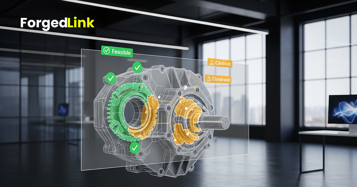
Many engineering designs look perfectly correct in CAD software but reveal manufacturing challenges once production begins. A part may appear simple in a digital model, yet the geometry could be difficult or inefficient to produce using real manufacturing processes.
This is why geometry feasibility checks are an important step before requesting manufacturing quotes. By validating the geometry of a part early, engineers can identify design issues that would otherwise cause delays, increased costs, or multiple rounds of revision with suppliers.
A geometry feasibility review helps answer a simple but critical question: Can this part actually be manufactured efficiently using the intended process?
Why Geometry Feasibility Matters
Manufacturers frequently receive CAD files that require additional engineering clarification before they can be quoted or produced. These delays often occur because the geometry introduces manufacturing challenges that were not considered during the design phase.
Common examples include deep cavities that cannot be reached by cutting tools, unsupported features in additive manufacturing, or thin walls that are difficult to machine reliably.
By identifying these issues before sourcing suppliers, engineers can reduce unnecessary back-and-forth communication and improve the overall efficiency of the manufacturing workflow.
Key Geometry Checks Engineers Should Perform
A practical geometry validation process typically includes several important checks.
1. Wall Thickness
Wall thickness is one of the most common manufacturability issues. Walls that are too thin may deform during machining or printing, while walls that are too thick can create unnecessary weight and material cost.
- Ensure wall thickness meets minimum manufacturing limits
- Avoid sudden transitions between thin and thick areas
- Consider structural reinforcement if thin walls are required
Different manufacturing processes have different minimum wall thickness recommendations.
2. Tool Accessibility
For CNC machining, cutting tools must physically reach the features they are intended to produce. Designs that include narrow internal cavities or deep pockets can be difficult or impossible to machine.
- Ensure cutting tools can access internal features
- Avoid extremely narrow slots or cavities
- Reduce pocket depth where possible
Improving tool accessibility often reduces machining time and manufacturing cost.
3. Overhangs and Support Structures
In additive manufacturing, unsupported overhangs can lead to poor surface quality or failed prints. Metal 3D printing processes such as selective laser melting require support structures for certain geometries.
- Review overhang angles for additive manufacturing
- Consider how support structures will be removed
- Avoid enclosed voids that trap powder
Designing with additive constraints in mind improves print reliability and post-processing efficiency.
4. Internal Corners and Radii
Sharp internal corners are difficult to produce with most manufacturing methods. Machining tools naturally produce rounded internal corners due to the tool diameter.
- Add internal radii where possible
- Avoid extremely sharp internal corners
- Use consistent corner radii across the design
This adjustment often simplifies machining and reduces tool wear.
5. Feature Complexity
Highly complex geometry may increase manufacturing cost without providing functional benefits. Engineers should review whether features can be simplified without compromising performance.
- Remove unnecessary small details
- Simplify repeated features
- Evaluate whether complex geometry adds real functional value
In many cases, simpler geometry results in faster and more reliable production.
Process-Specific Geometry Considerations
Manufacturing constraints vary depending on the production method used. A design that works well for one process may be difficult to produce using another.
For example:
- CNC machining requires tool access and manageable feature depth
- Metal additive manufacturing requires support structures for overhangs
- Sheet metal fabrication requires bend allowances and minimum radii
Understanding these differences helps engineers choose the most suitable process for their design.
Common Geometry Issues That Delay Manufacturing
Manufacturers frequently encounter similar geometry challenges when reviewing new designs.
- Walls that are too thin for reliable production
- Deep pockets that require specialised tooling
- Sharp internal corners incompatible with machining
- Unsupported overhangs in additive manufacturing
- Complex internal features that cannot be accessed
Identifying these issues early helps prevent production delays and redesign cycles.
Using Geometry Validation Tools
Modern engineering workflows increasingly rely on automated validation tools to evaluate CAD models before production.
These tools analyse geometry and highlight features that may create manufacturing challenges. Engineers can then adjust the design before sending the part to suppliers.
Typical geometry validation tools review:
- Wall thickness
- Feature accessibility
- Overhang angles
- Minimum radii
- Process compatibility
This type of automated validation helps ensure designs are production-ready.
Conclusion
Validating part geometry before sourcing manufacturers is a critical step in modern engineering workflows. By reviewing wall thickness, tool accessibility, internal corners, and process-specific constraints, engineers can significantly improve manufacturability.
A structured geometry feasibility review reduces production delays, improves supplier communication, and helps ensure designs move smoothly from concept to production.
CTA: Test your part geometry before sourcing manufacturing suppliers.