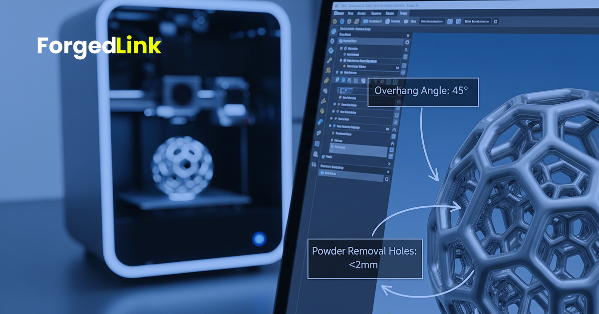
Metal additive manufacturing has moved from prototyping to real production applications across aerospace, medical, automotive, and advanced engineering industries. Technologies such as Selective Laser Melting (SLM) and Direct Metal Laser Sintering (DMLS) allow manufacturers to produce complex geometries that would be impossible or prohibitively expensive using traditional machining.
However, successful metal 3D printing does not start with the machine—it starts with the design. Parts originally designed for CNC machining or casting often perform poorly when sent directly to an additive manufacturing process.
Understanding the key design rules for metal 3D printing can significantly improve build success rates, reduce cost, and shorten production timelines.
Why Designing for Additive Manufacturing Matters
Unlike subtractive processes such as CNC machining, metal 3D printing builds components layer by layer. This enables exceptional geometric freedom, but also introduces new constraints related to heat, support structures, and material behaviour.
Designing with these constraints in mind allows engineers to take full advantage of additive manufacturing while avoiding costly redesigns later in the production workflow.
Common challenges engineers encounter when designing for metal 3D printing include:
- Unsupported overhangs that require excessive support structures
- Internal channels that trap powder after printing
- Wall thicknesses that are too thin to print reliably
- Large flat surfaces that deform due to thermal stress
- Geometry that significantly increases build time and cost
These issues can often be avoided with a few core design principles.
Key Design Rules for Metal 3D Printing
1. Respect Minimum Wall Thickness
Thin walls are one of the most common causes of print failure in metal additive manufacturing. While machines are capable of producing fine features, extremely thin walls may warp or fail during the build process.
As a general guideline:
- Structural walls should typically be at least 0.8–1.2 mm thick
- Small features or fins should be designed thicker where possible
- Thin unsupported structures should be avoided
Designing slightly thicker features often improves both reliability and mechanical performance.
2. Manage Overhang Angles
Overhangs are surfaces that extend outward during the build process without support from the layers below. Metal additive manufacturing generally requires support structures for overhangs exceeding a certain angle.
Typical design guidelines include:
- Overhangs below 45° usually require support structures
- Angles above 45° often print successfully without support
- Reducing unnecessary overhangs can reduce post-processing costs
Careful orientation of the part within the build chamber can also minimise support requirements.
3. Design for Powder Removal
Metal powder remains inside cavities and internal channels during the printing process. If parts include enclosed volumes without escape paths, the powder may become trapped inside the component.
Designers should consider:
- Adding powder escape holes
- Ensuring internal channels remain accessible
- Avoiding completely sealed internal volumes
This is particularly important for heat exchangers, lattice structures, and internal fluid channels.
4. Avoid Large Flat Surfaces
Large flat surfaces are prone to thermal distortion during metal printing due to residual stresses created by rapid heating and cooling.
Instead of large flat plates, engineers often achieve better results by:
- Adding ribs or structural features
- Breaking up large surfaces into smaller geometric sections
- Introducing curvature where possible
These design adjustments can dramatically improve print stability.
5. Consolidate Complex Assemblies
One of the most powerful advantages of additive manufacturing is the ability to combine multiple parts into a single printed component.
Part consolidation can:
- Reduce assembly time
- Eliminate fasteners or welds
- Improve mechanical reliability
- Reduce supply chain complexity
Many aerospace and medical applications already use additive manufacturing to simplify complex assemblies.
SLM vs DMLS: What Designers Should Know
SLM and DMLS are often used interchangeably, but both processes involve laser-based fusion of metal powder within a controlled environment.
From a design perspective, the same core principles apply:
- Manage thermal stresses through smart geometry
- Minimise support structures where possible
- Ensure proper powder removal
- Design for post-processing and finishing
While machine capabilities vary slightly between suppliers, these design fundamentals remain consistent across most metal additive manufacturing platforms.
Common Design Mistakes in Metal 3D Printing
Even experienced engineers sometimes apply traditional manufacturing assumptions when designing parts for additive manufacturing.
Some of the most common mistakes include:
- Designing parts exactly as they would be machined
- Ignoring build orientation during design
- Failing to account for post-processing operations
- Creating internal cavities that trap powder
- Overcomplicating geometry without functional benefit
Early manufacturability validation can prevent many of these issues before a part reaches the production stage.
From Design to Production
Metal additive manufacturing is most powerful when design decisions are aligned with manufacturing constraints from the start. Engineers who incorporate additive design principles early in the workflow often achieve better part performance, lower cost, and shorter development cycles.
Before submitting a design for metal 3D printing, it is useful to validate whether the geometry, wall thickness, and internal features are compatible with the process.
Doing so can prevent costly delays and ensure the design is ready for production.
Next Step: Check whether your part geometry is suitable for additive manufacturing before sending it to suppliers.